Mercotac Four Conductor
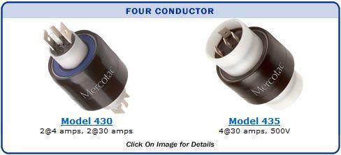
Model 430
Four Conductors,
2@4amps, 2@30amps
|
 |

|
Disconnects included
(4 sm., 4 lg.)
Boot kit available
Available with stainless steel ball bearing (430-SS) |
| Mercotac model 430 is ideal for heated roller applications, where connecting to senstive thermocouple signals and simultaneously powering the heater are required. |
|
|
| Model No. |
Terminals |
Voltage
AC/DC |
Amp
Rating
@240VAC |
Max.
Freq.
MHz |
Contact
Resistance |
Max.
RPM |
Temp
Max. F (C) /
Min. F (C) |
Rotation
Torque (gm-cm) |
Circuit
Separation |
| 430 |
4 |
0-250 |
2@4/2@30 |
100 |
|
<1m
|
 |
|
1200 |
140 (60) /-20(-29) |
400 |
|
>25M
|
|
|
| 430-SS |
4 |
0-250 |
2@4/2@30 |
100 |
|
<1m
|
|
|
1200 |
140 (60) /-20(-29) |
400 |
|
>25M
|
|
|
"SS" designator indicates stainless steel ball bearing (recommended for wet or corrosive environments)
 Model 430 Accessories Model 430 Accessories |
|
|
 |
50431
Plug Assembly 12 in. wires
14 AWG & 18 AWG
Suitable for up to 20 Amps |
50430
Plug Kit - No wires, terminals for wire gauges
20 - 16 AWG & 16 - 14 AWG
Suitable for up to 20 Amps
Also order 5030-T |
 |
 |
57430
Boot Kit for dust or splash protection
IP51 |
55251
Terminal 16 - 14 AWG
(qty. 2 included) |
 |
 |
5030-T
Plug Terminal Crimping Tool
For Use With 50430 Kit |
55250
16 - 14 AWG (qty. 2 included) |
|
 |
|
55110
22 - 18 AWG (qty. 4 included) |
|
Terminals for other wire gauges available.
(22-18 AWG and 12-10 AWG)
|
|
| Model 430 Standard Wire Connections |
| Model 430 Wire Connections With Optional Boot |
|
|
| Model 430 Suggested Mounting Methods |
| Model 430 is typically mounted by either the black body or the white plastic bushing on either end using a set screw. When mounting horizontally, mount the Mercotac so the body of the connector rotates. |
|
|
Typical Body Mount Hole Dimensions
|
| MODEL |
HOLE DIAMETER (Ø) * |
DEPTH |
| 430, et al |
1.248" (31.70) |
.80" (20) |
|
|
|
|
Typical Bushing Mount Hole Dimensions
|
| 430, et al |
.625" (15.88) |
.40" (10) |
| With Plug Connector |
.625" (15.88) |
1.40" (36) |
| *Inch (mm) Tolerance Ø |
+.001" (+.025) |
|
|
| |
-.000" (-.000) |
|
|
|
|
Installation Notes:
- the up arrow should not point below horizontal
- do not solder to or bend connector tabs
- avoid lateral forces and mechanical loads (overly stiff or tight wires)
- do not rigid mount both ends of connector
- limit mounting eccentricity (runout / wobble) to .005" (.13mm)
- provide overload protection within the circuit
- avoid vibration and bumping motions
|
Model 435
Four Conductors,
4@30amps & 500V
|
 |

|
Disconnects included
(8 lg.)
Boot kit available
Available with stainless steel ball bearing (435-SS) |
|
| Model No. |
Terminals |
Voltage
AC/DC |
Amp
Rating
@500VAC |
Max.
Freq.
MHz |
Contact
Resistance |
Max.
RPM |
Temp
Max. F (C) /
Min. F (C) |
Rotation
Torque (gm-cm) |
Circuit
Separation |
| 435 |
4 |
0-500 |
30 |
100 |
|
<1m
|
|
|
300 |
140 (60) /-20(-29) |
850 |
|
>50M
|
|
|
| 435-SS |
4 |
0-500 |
30 |
100 |
|
<1m
|
|
|
300 |
140 (60) /-20(-29) |
850 |
|
>50M
|
|
|
"SS" designator indicates stainless steel ball bearing (recommended for wet or corrosive environments)
| Model 435 Accessories |
|
|
 |
55250
16 - 14 AWG (qty. 4 included) |
55251
Terminal 16 - 14 AWG
(qty. 4 included) |
57435
Boot Kit for dust or splash protection
IP51 |
|
Terminals for other wire gauges available.
(22-18 AWG and 12-10 AWG)
|
|
| Model 435 Standard Wire Connections |
| Model 435 Wire Connections With Optional Boot Kit |
|
|
| Model 435 Suggested Mounting Methods |
| Model 435 is typically mounted by either the black body or the white plastic bushing on either end using a set screw. When mounting horizontally, mount the Mercotac so the body of the connector rotates. |
|
|
Typical Body Mount Hole Dimensions
|
| MODEL |
HOLE DIAMETER (Ø) * |
DEPTH |
| 435, et al |
1.772" (45.00) |
.80" (20) |
|
|
|
|
Typical Bushing Mount Hole Dimensions
|
| 435, et al |
1.250" (31.75) |
.80" (20) |
| *Inch (mm) Tolerance Ø |
+.001" (+.025) |
|
|
| |
-.000" (-.000) |
|
|
|
|
Installation Notes:
- the up arrow should not point below horizontal
- do not solder to or bend connector tabs
- avoid lateral forces and mechanical loads (overly stiff or tight wires)
- do not rigid mount both ends of connector
- limit mounting eccentricity (runout / wobble) to .005" (.13mm)
- provide overload protection within the circuit
- avoid vibration and bumping motions
|