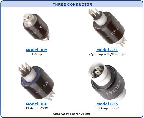
Mercotac Three Conductor
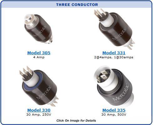
Model 305
Three Conductors,
4 Amps
|
 |

|
Stainless steel ball bearing standard |
|
| Model No. |
Terminals |
Voltage
AC/DC |
Amp
Rating
@240VAC |
Max.
Freq.
MHz |
Contact
Resistance |
Max.
RPM |
Temp
Max. F (C) /
Min. F (C) |
Rotation
Torque (gm-cm) |
Circuit
Separation |
| 305 |
3 |
0-250 |
4 |
200 |
|
<1m
|
 |
|
1800 |
140 (60) /45(7) |
100 |
|
>25M
|
|
|
| 305-L |
3 |
0-250 |
4 |
200 |
|
<1m
|
|
|
1000 |
140 (60) /-20(-29) |
100 |
|
>25M
|
|
|
"L" designator indicates low temp.
 Model 305 Accessories Model 305 Accessories |
 |
 |
593
three contact receptacle w/ 6" wires (18 AWG) |
553
three contact cap
w/solder lugs |
|
Receptacle used for mounting to rotating device.
Accessories required for wire connections. Order Separately.

|
|
| Model 305 Connections |
|

|

|
| Note: The outer shell of the metal receptacle used for mounting is electrically conductive. |
| Model 305 Suggested Mounting Methods |
| Model 305 is typically mounted by the knurled metal receptacle, which is press-fit into the rotating member of the machine. When mounting horizontally, mount the Mercotac so the body of the connector rotates. |
|
|
Receptacle Mount Hole Dimensions
|
| MODEL |
HOLE DIAMETER (Ø) * |
DEPTH |
| 593 |
.408" (10.36) |
.35" (8.89) |
| *Inch (mm) Tolerance Ø |
+.001" (+.025) |
|
|
|
-.000" (-.000) |
|
|
|
Installation Notes:
- the up arrow should not point below horizontal
- do not solder to or bend connector tabs
- avoid lateral forces and mechanical loads (overly stiff or tight wires)
- do not rigid mount both ends of connector
- limit mounting eccentricity (runout / wobble) to .005" (.13mm)
- provide overload protection within the circuit
- avoid vibration and bumping motions
|
Model 330
Three Conductors,
30 amps
|
 |

|
Disconnects included (6 lg.)
Boot kit available
Available with stainless steel ball bearing (330-SS) |
|
| Model No. |
Terminals |
Voltage
AC/DC |
Amp
Rating
@240VAC |
Max.
Freq.
MHz |
Contact
Resistance |
Max.
RPM |
Temp
Max. F (C) /
Min. F (C) |
Rotation
Torque (gm-cm) |
Circuit
Separation |
| 330 |
3 |
0-250 |
30 |
100 |
|
<1m
|
|
|
1200 |
140 (60) /-20(-29) |
300 |
|
>25M
|
|
|
| 330-SS |
3 |
0-250 |
30 |
100 |
|
<1m
|
|
|
1200 |
140 (60) /-20(-29) |
300 |
|
>25M
|
|
|
"SS" designator indicates stainless steel ball bearing (recommended for wet or corrosive environments)
| Model 330 Accessories |
 |
 |
55251
Terminal 16 - 14 AWG
(qty. 3 included) |
57430
Boot Kit for dust or splash protection
IP51 |
 |
 |
55253
Shrink Tube (qty. 3 included) |
55252
Terminal 16 - 14 AWG (qty. 3 included) |
|
|
Terminals for other wire gauges available.
(22-18 AWG and 12-10 AWG)
|
|
|
| Model 330 Standard Wire Connections |
| Model 330 Wire Connections With Optional Boot Kit |
|
|
| Model 330 Suggested Mounting Methods |
| Model 330 is typically mounted by either the black body or the white plastic bushing on either end using a set screw. When mounting horizontally, mount the Mercotac so the body of the connector rotates. |
|
|
Typical Body Mount Hole Dimensions
|
| MODEL |
HOLE DIAMETER (Ø) * |
DEPTH |
| 330 et al |
1.248" (31.70) |
.80" (20) |
|
|
|
|
Typical Bushing Mount Hole Dimensions
|
| 330 et al |
.625" (15.88) |
.40" (10) |
| *Inch (mm) Tolerance Ø |
+.001" (+.025) |
|
|
| |
-.000" (-.000) |
|
|
|
|
Installation Notes:
- the up arrow should not point below horizontal
- do not solder to or bend connector tabs
- avoid lateral forces and mechanical loads (overly stiff or tight wires)
- do not rigid mount both ends of connector
- limit mounting eccentricity (runout / wobble) to .005" (.13mm)
- provide overload protection within the circuit
- avoid vibration and bumping motions
|
Model 331
Three Conductors,
2@4amps, 1@30amps
|
 |

|
Disconnects included
(4 sm., 2 lg.)
Boot kit available
Available with stainless steel ball bearing (331-SS) |
|
| Model No. |
Terminals |
Voltage
AC/DC |
Amp
Rating
@240VAC |
Max.
Freq.
MHz |
Contact
Resistance |
Max.
RPM |
Temp
Max. F (C) /
Min. F (C) |
Rotation
Torque (gm-cm) |
Circuit
Separation |
| 331 |
3 |
0-250 |
2@4/1@30 |
100 |
|
<1m
|
|
|
1800 |
140 (60) /-20(-29) |
200 |
|
>25M
|
|
|
| 331-SS |
3 |
0-250 |
2@4/1@30 |
100 |
|
<1m
|
|
|
1800 |
140 (60) /-20(-29) |
200 |
|
>25M
|
|
|
"SS" designator indicates stainless steel ball bearing (recommended for wet or corrosive environments)
| Model 331 Accessories |
|
 |
55251
Terminal 16 - 14 AWG
(qty. 1 included) |
57230
Boot Kit for dust / splash protection
IP51 |
 |
 |
55250
16 - 14 AWG (qty. 1 included) |
55110
22 - 18 AWG (qty. 4 included) |
|
|
Terminals for other wire gauges available.
(22-18 AWG and 12-10 AWG)
|
|
|
| Model 331 Standard Wire Connections |
| Model 331 Wire Connections With Optional Boot Kit |
|
|
| Model 331 Suggested Mounting Methods |
| Model 331 is typically mounted by either the black body or the white plastic bushing on either end using a set screw. When mounting horizontally, mount the Mercotac so the body of the connector rotates. |
|
|
Typical Body Mount Hole Dimensions
|
| MODEL |
HOLE DIAMETER (Ø) * |
DEPTH |
| 331 et al |
.998" (25.35) |
.80" (20) |
|
|
|
| Typical Bushing Mount Hole Dimensions |
| 331 et al |
.500" (12.70) |
.40" (10) |
| *Inch (mm) Tolerance Ø |
+.001" (+.025) |
|
|
| |
-.000" (-.000) |
|
|
|
|
Installation Notes:
- the up arrow should not point below horizontal
- do not solder to or bend connector tabs
- avoid lateral forces and mechanical loads (overly stiff or tight wires)
- do not rigid mount both ends of connector
- limit mounting eccentricity (runout / wobble) to .005" (.13mm)
- provide overload protection within the circuit
- avoid vibration and bumping motions
|
Model 335
Three Conductors,
3@30amps & 500V
|
 |

|
Disconnects included (6 lg.)
Boot Kit available
Available with stainless steel
ball bearing (335-SS) |
|
| Model No. |
Terminals |
Voltage
AC/DC |
Amp
Rating
@500VAC |
Max.
Freq.
MHz |
Contact
Resistance |
Max.
RPM |
Temp
Max. F (C) /
Min. F (C) |
Rotation
Torque (gm-cm) |
Circuit
Separation |
| 335 |
3 |
0-500 |
30 |
100 |
|
<1m
|
|
|
500 |
140 (60) /-20(-29) |
700 |
|
>50M
|
|
|
| 335-SS |
3 |
0-500 |
30 |
100 |
|
<1m
|
|
|
500 |
140 (60) /-20(-29) |
700 |
|
>50M
|
|
|
"SS" designator indicates stainless steel ball bearing (recommended for wet or corrosive environments)
| Model 335 Accessories |
 |
|
|
57335
Boot Kit for dust or splash
protection IP51 |
55250
Terminal 16 - 14 AWG
(qty. 3 included) |
55251
Terminal 16 - 14 AWG
(qty. 3 included) |
| |
Terminals for other wire gauges available.
(22-18 AWG and 12-10 AWG)
|
|
| Model 335 Standard Wire Connections |
| Model 335 Wire Connections With Optional Boot |
|
|
| Model 335 Suggested Mounting Methods |
| Model 335 is typically mounted by either the black body or the white plastic bushing on either end using a set screw. When mounting horizontally, mount the Mercotac so the body of the connector rotates. |
|
|
Typical Body Mount Hole Dimensions
|
| MODEL |
HOLE DIAMETER (Ø) * |
DEPTH |
| 335, et al |
1.575" (40.0) |
.80" (20.3) |
|
|
|
|
Typical Bushing Mount Hole Dimensions
|
| 335, et al |
.984" (25.0) |
.80" (20.3) |
| *Inch (mm) Tolerance Ø |
+.001" (+.025) |
|
|
| |
-.000" (-.000) |
|
|
|
|
Installation Notes:
- the up arrow should not point below horizontal
- do not solder to or bend connector tabs
- avoid lateral forces and mechanical loads (overly stiff or tight wires)
- do not rigid mount both ends of connector
- limit mounting eccentricity (runout / wobble) to .005" (.13mm)
- provide overload protection within the circuit
- avoid vibration and bumping motions
|