Mercotac - One Conductor
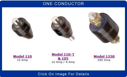
Model 110
One Conductor,
10 Amp
|
 |

|
Mounts at the end of a rotating axis.
Mount by the press fit receptacle accessory.
Wire attaches using the accessory receptacle or cap.
This model is designed to mount at the bottom of a vertical rotating shaft. |
|
| Model No. |
Terminals |
Voltage
AC/DC |
Amp
Rating
@240VAC |
Max.
Freq.
MHz |
Contact
Resistance |
Max.
RPM |
Temp
Max. F (C) /
Min. F (C) |
Rotation
Torque (gm-cm) |
Circuit
Separation |
| 110 |
1 |
N/A |
10 |
200 |
|
<1m
|
 |
|
3600 |
140 (60) /-20(-29) |
35 |
N/A |
| 110-SS |
1 |
N/A |
10 |
200 |
|
<1m
|
|
|
3600 |
140 (60) /-20(-29) |
35 |
N/A |
| 110-L |
1 |
N/A |
10 |
200 |
|
<1m
|
|
|
1200 |
140 (60) /-20(-29) |
10 |
N/A |
"SS" designator indicates stainless steel ball bearing (recommended for wet or corrosive environments)
"L" designator indicates low torque
Note: The anodized aluminum housing of the 110 series Mercotac is electrically "hot" to the internal conductor.
 Model 110 Accessories Model 110 Accessories |
|
| Model 110 Connections |
|

|

|
| Note: The metal receptacle used for mounting is electrically conductive. Therefore, if desired, it can be used as the electrical connection between the 110 and the rotating member of the machine using Part #5920. However, if an insulated mounting at the rotating member is being used, then Part #5921-S with six inch wire lead is used for the electrical connection. |
| Model 110 Suggested Mounting Methods |
| Model 110 is typically mounted by the knurled metal receptacle, which is press-fit into the rotating member of the machine. When mounting horizontally, use the similar model 110-T instead to be able to mount the Mercotac rotary connector so that the body of the connector rotates. |
|
|
Receptacle Mount Hole Dimensions
|
| MODEL |
HOLE DIAMETER (Ø) * |
DEPTH |
| 5920, 5921-S |
.283" (7.19) |
.35" (8.89) |
| *Inch (mm) Tolerance Ø |
+.001" (+.025) |
|
|
| |
-.000" (-.000) |
|
|
|
|
Installation Notes:
- the up arrow should not point below horizontal
- do not solder to or bend connector tabs
- avoid lateral forces and mechanical loads (overly stiff or tight wires)
- do not rigid mount both ends of connector
- limit mounting eccentricity (runout / wobble) to .005" (.13mm)
- provide overload protection within the circuit
- avoid vibration and bumping motions
|
Model 110-T
One Conductor,
10 Amp
Model 105
One Conductor,
4 Amp |
 |

|
Mounts at the end of a rotating axis.
Mount by the press fit receptacle accessory.
Wires attach using the accessory receptacle and cap. |
| Mercotac models 110-T & 105 are ideal for shaft grounding applications, including HVAC and VFD motor shaft grounding, thus avoiding very costly bearing damage. |
|
|
| Model No. |
Terminals |
Voltage
AC/DC |
Amp
Rating
@240VAC |
Max.
Freq.
MHz |
Contact
Resistance |
Max.
RPM |
Temp
Max. F (C) /
Min. F (C) |
Rotation
Torque (gm-cm) |
Circuit
Separation |
| 110-T |
1 |
N/A |
10 |
200 |
|
<1m
|
|
|
3600 |
140 (60) /-20(-29) |
35 |
N/A |
| 110-TS |
1 |
N/A |
10 |
200 |
|
<1m
|
|
|
3600 |
140 (60) /-20(-29) |
35 |
N/A |
| 110-TL |
1 |
N/A |
10 |
200 |
|
<1m
|
|
|
1200 |
140 (60) /-20(-29) |
10 |
N/A |
| 105 * |
1 |
N/A |
4 |
200 |
|
<1m
|
|
|
7500 |
212 (100) /45(7) |
<10 |
N/A |
| 105-SS * |
1 |
N/A |
4 |
200 |
|
<1m
|
|
|
7500 |
212 (100) /45(7) |
<10 |
N/A |
"T" designator indicates standard model
"TS" designator indicates stainless steel ball bearing (recommended for wet or corrosive environments)
"TL" designator indicates low torque
"SS" designator indicates stainless steel ball bearing (recommended for wet or corrosive environments)
* indicates high temp. high RPM
Note: The anodized aluminum housing of the 110 & 105series Mercotac is electrically "hot" to the internal conductor.
| Model 110-T & 105 Accessories |
|
| Model 110-T & 105 Connections |
|

|

|
| Note: The metal receptacle used for mounting is electrically conductive. Therefore, if desired, it can be used as the electrical connection between the 110 and the rotating member of the machine using Part #5920. However, if an insulated mounting at the rotating member is being used, then Part #5921-S with six inch wire lead is used for the electrical connection. |
| Model 110-T & 105 Suggested Mounting Methods |
| Model 110-T is typically mounted by the knurled metal receptacle, which is press-fit into the rotating member of the machine When mounting horizontally, mount the Mercotac so the body of the connector rotates. |
|
|
Receptacle Mount Hole Dimensions
|
| MODEL |
HOLE DIAMETER (Ø) * |
DEPTH |
| 5920, 5921-S |
.283" (7.19) |
.35" (8.89) |
| *Inch (mm) Tolerance Ø |
+.001" (+.025) |
|
|
| |
-.000" (-.000) |
|
|
|
|
Installation Notes:
- the up arrow should not point below horizontal
- do not solder to or bend connector tabs
- avoid lateral forces and mechanical loads (overly stiff or tight wires)
- do not rigid mount both ends of connector
- limit mounting eccentricity (runout / wobble) to .005" (.13mm)
- provide overload protection within the circuit
- avoid vibration and bumping motions
|
|
Model 1250
One Conductor,
250 Amp
|
 |

|
|
4 nuts included
Boot kit available
Available in metric thread (1250-M)
Available with stainless steel ball bearing (1250-SS) (recommended for wet or corrosive environments)
Available with stainless steel body and bearing (1250-SX / 1250-MSX) (recommended for wet or corrosive environments) |
| Mercotac model 1250 series are ideal connectors for high-power applications such as on plating electrodes and welding cable reels. |
|
|
| Model No. |
Terminals |
Voltage
AC/DC |
Amp
Rating
@240VAC |
Max.
Freq.
MHz |
Contact
Resistance |
Max.
RPM |
Temp
Max. F (C) /
Min. F (C) |
Rotation
Torque (gm-cm) |
Circuit
Separation |
| 1250 |
1 |
N/A |
250 |
200 |
|
<1m
|
|
|
1200 |
140 (60) /-20(-29) |
250 |
N/A |
| 1250-SS |
1 |
N/A |
250 |
200 |
|
<1m
|
|
|
1200 |
140 (60) /-20(-29) |
250 |
N/A |
| 1250-M |
1 |
N/A |
250 |
200 |
|
<1m
|
|
|
1200 |
140 (60) /-20(-29) |
250 |
N/A |
| 1250-MS |
1 |
N/A |
250 |
200 |
|
<1m
|
|
|
1200 |
140 (60) /-20(-29) |
250 |
N/A |
| 1250-SX |
1 |
N/A |
250 |
200 |
|
<1m
|
|
|
1200 |
140 (60) /-20(-29) |
250 |
N/A |
| 1250-MSX |
1 |
N/A |
250 |
200 |
|
<1m
|
|
|
1200 |
140 (60) /-20(-29) |
250 |
N/A |
"SS" designator indicates stainless steel ball bearing
"M" designator indicates metric thread (M10 x 1.5)
"MS" designator indicates metric thread & stainless steel ball bearing
"SX" designator indicates stainless steel body & bearing
"MSX" designator indicates metric thread & stainless steel body & bearing
Note: The housing of the 1250 series Mercotac connector (anodized aluminum or stainless steel) is electrically "hot" to the internal conductor.
| Model 1250 Accessories |
|
 |
|
|
57125
Book Kit for dust and splash protection
IP51 |
|
|
|
| Model 1250 Connections |
| Model 1250 Suggested Mounting Methods |
| Model 1250 is typically mounted by the threaded stud on either end or by the black body using a set screw. When mounting horizontally, mount the Mercotac so the body of the connector rotates. |
|
|
Typical Body Mount Dimensions
|
| MODEL |
HOLE DIAMETER (Ø) * |
DEPTH |
| 1250, et al |
1.248" (31.70) |
.80" (20.0) |
|
|
|
|
Typical Threaded Contact Mount
|
| 1250 (inch) |
3/8 - 16 UNC |
.70" (17.8) |
| 1250-M (metric) |
M10 X 1.5 |
.70" (17.8) |
| *Inch (mm) Tolerance Ø |
+.001" (+.025) |
|
|
| |
-.000" (-.000) |
|
|
|
|
Installation Notes:
- the up arrow should not point below horizontal
- do not solder to or bend connector tabs
- avoid lateral forces and mechanical loads (overly stiff or tight wires)
- do not rigid mount both ends of connector
- limit mounting eccentricity (runout / wobble) to .005" (.13mm)
- provide overload protection within the circuit
- avoid vibration and bumping motions
|
|